Enhanced oil recovery (EOR) chip - topconnect

SKU
EOR
Availability:
check_circle In stock
As low as $718.55

per pack of 3

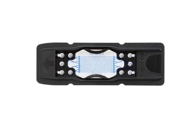
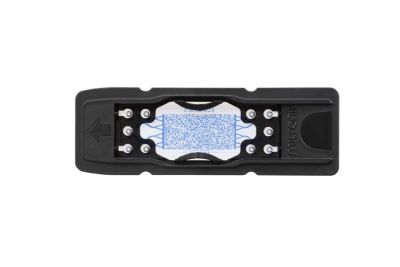
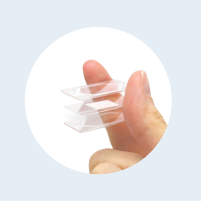
Enhanced oil recovery chips can be used to verify calculation models, providing an optical clear surrogate rock. Known geometrical conditions and optical clear chips create optimal conditions to study physical processes that normally occur inside rock formations.


Our Enhanced Oil Recovery chips mimick porous medium and are often used for veryfing and development of computer simulation models, development of elmulsification chemcials or other chemicals that enhance oil production,  microbiological enhanced oil production, research on effects of gas injections in oil fields.
The chips are available in three designs as listed below and can be supplied with or without a hydrophobic coating. By default glass behaves hydrophilic. The optional coating is applied on a best effort base, it is possible that some areas where geometries are not interconnected will stay uncoated.

Physical rock network

This chip is designed by randomly placing rock shaped structures on the chip to resemble the shape that is obtained by cutting rock as accurately as possible. This random structure results in throats and channels between the rock structures. This method of random placement does not give information on throat size distribution. For simulation purposes, the mask (2D) design is available on request. However, experience has taught us that the complexity of this structure makes it challenging to run computer simulations on.


Random network

Random network porous structure chip, often used for Chemical Enhanced Oil Recovery (CEOR) and Microbial Enhanced Oil Recovery (MEOR) experiments.


Uniform network

A systematically organized and well-defined rock-pore structure of equally sized pores and channels.


More Information
Unit of measurementpack of 3
Alternative item referencesEOR.PR.20.2, 02976, 01954; EOR.UN.20.2, 02978, 02198; EOR.RN.20.2, 02977, 02199
ApplicationEnhanced Oil Recovery
Interface typeTopconnect
Chip thickness1800µm
Chip materialBorosilicate glass
Number of inlets1
Number of outlets1
Supply format & dimensions

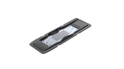
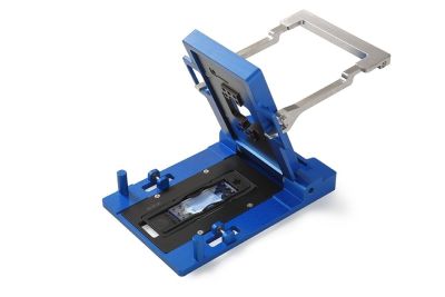
Supplied in black polymer cardtridge (polypropylene). The glass element has a size of 45x15mm. 

Permeability (Darcy)

EOR type

Permeability (Darcy)

Uniform Network

8.43-10.14

Physical Rock

6.62-7.79

Random Network

2.62-2.94

Icon Label Description Type Size Download
PDF EOR.UN.20.2 - Drawing Drawing for the EOR porous medium chip with Uniform Pore Network. Items 02978 and 02198 PDF 378.2 KB Download
PDF EOR.RN.20.2 - Drawing Drawing for the EOR porous medium chip with Random Pore Network. Items 02977 and 02199 PDF 123.7 KB Download
pdf EOR.PR.20.2 - Drawing Drawing for the EOR porous medium chip with a Physical Rock Network. Items 02976 and 01954 pdf 139.5 KB Download
pdf Permeability determination of catalogue chips This documents describes how permeability values of EOR chips with a Uniform Network, Random Network and Physical Rock network are determent. pdf 983.2 KB Download
Customer Questions
How do I clean my chips?
One simple but very effective way to clean a microchip is to flush an alkaline solution through the channels. A solution of 1 M sodium hydroxide in water works well, but a lower concentration might also be sufficient. If traces of the cleaning solution remain inside the chip after cleaning, rinse with water or ammonia. Further, plastic parts should not be exposed to alkaline solutions.
To remove particulate matter from your chip, a water bath with ultrasonic agitation can be used, preferably while flushing a watery solution through the channels.
Glass microchips can be heated (e.g. 400°C) causing any organic material on the glass surface to degrade. Try to use lower temperatures first because burning the content could make it stick. Make sure you only heat the glass chip and not the plastic parts around it.
Concentrated sulfuric acid works well to dissolve organic material, such as fibres, that are difficult to remove with alkaline solutions. Always keep in mind that you are working with extremely corrosive material. Please note that this instruction is focused on the chip itself, PEEK elements like connectors are not so compatible with strong sulforic acid.
Please note that chips that were coated by Micronit have different guidelines for cleaning!
Which pressure and temperature can the EOR chip hold?
The EOR chip itself is manufactured from glass and can easily withstand up to 300⁰C. The chips are supplied in a black fluidic cartridge however, this cartridge can withstand up to 80⁰C.
No sealant is used, the two layers of glass are fusion bonded together.
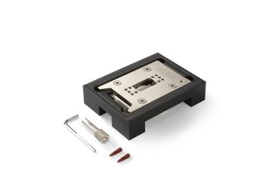
The chip can withstand easily up to 100 bar. The external interfacing is more critical however. Our Fluidic Connect holder offers the largest pressure, up to 80 bars (maybe less at elevated temperatures). Please note that it might be helpful to practice a little with the Fluidic Connect holder first. You need to get the feeling to apply not too much force, which might break the chip, but enough to obtain sufficient sealing. It might be necessary to tighten a bit more when pressure and temperature are increased. Please remove the pressure before additional tightening.
I'm using the Fluidic Connect 4515 holder (part of high pressure bundle), what alignment and fluidic port should I use?
The fluidic ports are on positions 3,8
Alignment can be done on positions 2,7 (or 4,9).
What's important in selection of a suitable microscope objective (regular bottom thickness chips)?
A inverted miscope is recommend, as most surface for observation is on the bottom (non-inlet side).
The objective working distance is a critical parameter for selection of an objective.  Most default objectives are indented for a #1.5 cover slip which is only 170µm thick, where the thickness below channel is mostly in the range of 400-900µm.   
Those objectives with longer working distance are often called non-coverglass objectives.
Where possible we would recommend to work dry. In most cases it should be possible to use the channel edge or other well defined point  as reference for manual size corrections, this would reduce the need for corrections by the objective.
What is the roughness of the etched structures?
Wet etched structures are extremely smooth and have a roughness in Angstrom range. The structures are fully optical transparent. 
Large roughness for structures in glass chips is typical observed for structures manufactured by use of laser assisted manufacturing techniques or abrasion-based techniques like powder blasting. Almost all catalogue products from Micronit are manufactured using wet etching to create full transparent channels without substantial roughness. 
Would you like to submit a question? Please login first.
We found other products you might like!
Copyright © 2020-present Micronit B.V. All rights reserved.