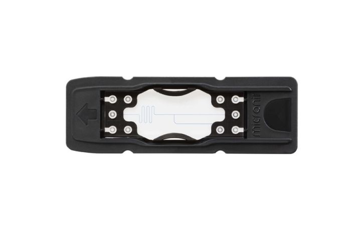
T-shaped droplet generator - topconnect

SKU
t-shaped
Availability:
check_circle In stock
As low as $627.35

per pack of 3

Pack of three T-shaped droplet generator chips.

Application area

Microfluidic droplet generators are excellent tools for generating highly reproducible microsized droplets with much higher precision and repeatability compared to conventional methods.

Such droplet can be aplied for:

  • Emulsification of a oil and water like substance 
  • Cell encapsulation, a (single) cell can be encapsulated to create it's own micro-environment and makes it easier to disinguish individual cell's. 
  • Creation of microparticles.

Chip details

The T-shaped dropletgnerator is the most classical type of droplet generator. By tuning the relative viscosities, surface tension, and velocities between the dispersed and the continuous phase, droplets of almost any size can be created.

Oil-in-Water (O/W) droplets can be generated directly using the glass chips. For Water-in-Oil droplets (W/O), choose the coated chips.

Chip design

The chip design is as follow:

More details can be found in the drawing.

The channels have a height of 20µm and width of 100µm and are etched in a single layer. This gives the following channel profile:


The chips contains a nozzle (half semi-oval) with a size of 34x10µm (width x height) that connects the sub-channel with the main-channel. 


More Information
Unit of measurementpack of 3
Interface typeTopconnect
Chip materialBorosilicate glass
Supply format & dimensions

Supplied in a black polymer cardtridge with an external dimension of 75 x 25mm.
The functional glass element has a size of 45x15mm.

Chip thickness1800µm
Number of inlets2
Number of outlets1
Icon Label Description Type Size Download
pdf TSDG.2 - T-shaped droplet generator pdf 67.3 KB Download
pdf Surface wetting properties pdf 220.3 KB Download
pdf Flow rate instructions pdf 303.6 KB Download
pdf How to prevent clogging pdf 153 KB Download
pdf Using the right surfactants pdf 168.8 KB Download
Customer Questions
How do I clean my chips?
One simple but very effective way to clean a microchip is to flush an alkaline solution through the channels. A solution of 1 M sodium hydroxide in water works well, but a lower concentration might also be sufficient. If traces of the cleaning solution remain inside the chip after cleaning, rinse with water or ammonia. Further, plastic parts should not be exposed to alkaline solutions.
To remove particulate matter from your chip, a water bath with ultrasonic agitation can be used, preferably while flushing a watery solution through the channels.
Glass microchips can be heated (e.g. 400°C) causing any organic material on the glass surface to degrade. Try to use lower temperatures first because burning the content could make it stick. Make sure you only heat the glass chip and not the plastic parts around it.
Concentrated sulfuric acid works well to dissolve organic material, such as fibres, that are difficult to remove with alkaline solutions. Always keep in mind that you are working with extremely corrosive material. Please note that this instruction is focused on the chip itself, PEEK elements like connectors are not so compatible with strong sulforic acid.
Please note that chips that were coated by Micronit have different guidelines for cleaning!
I need a pumping system for my setup. Which one do you recommend?
We recommend using a high precision pumping system. Regular syringe pumps often don't work very well for droplet generators. There are several high precision pumping systems on the market that work with different pumping principles. To name one, we'd like to mention that we have had positive experiences with the equipment Fluigent offers: https://www.fluigent.com/  
Which flowrates should I use?
This depends on many things. For example on the type of fluid that you are using. Check our flowrate instructions to find out how to start.
I only see streaks of fluids but no droplets. How do I get the droplets?
Decrease your flowrate. Check our flowrate instructions for a more acurate explanation.
Which surfactants should I use?
Use our surfactant guide for advice on surfactants.
How do I prevent clogging of my chips?
Have a look at our clogging prevention guide.
Should I use coated or uncoated droplet generators?
Have a look at our article about surface wetting properties.
Publication: Controlled and tunable polymer particles' production using a single microfluidic device
Amoyav, Benzion, and Ofra Benny "Controlled and tunable polymer particles’ production using a single microfluidic device." Applied Nanoscience (2018): 1-10. Abstract Microfluidics technology offers a new platform to control liquids under flow in small volumes. The advantage of using smallscale reactions for droplet generation along with the capacity to control the preparation parameters, making microfluidic chips an attractive technology for optimizing encapsulation formulations. However, one of the drawbacks in this methodology is the ability to obtain a wide range of droplet sizes, from sub-micron to microns using a single chip design. In fact, typically, droplet chips are used for micron-dimension particles, while nanoparticles’ synthesis requires complex chips design (i.e., microreactors and staggered herringbone micromixer). Here, we introduce the development of a highly tunable and controlled encapsulation technique, using two polymer compositions, for generating particles ranging from microns to nano-size using the same simple single microfluidic chip design. Poly(lactic-co-glycolic acid) (PLGA 50:50) or PLGA/polyethylene glycol polymeric particles were prepared with focused-flow chip, yielding monodisperse particle batches. We show that by varying flow rate, solvent, surfactant and polymer composition, we were able to optimize particles’ size and decrease polydispersity index, using simple chip designs with no further related adjustments or costs. Utilizing this platform, which offers tight tuning of particle properties, could offer an important tool for formulation development and can potentially pave the way towards a better precision nanomedicine. Keywords: Microfluidics · Nanoparticles · Microparticles · Polymeric particles · Focused flow
Publication: Spatiotemporal variation of endogenous cell-generated stresses within 3D multicellular spheroids
Lucio, Adam A., et al. "Spatiotemporal variation of endogenous cell-generated stresses within 3D multicellular spheroids." Scientific reports 7.1 (2017): 12022. Abstract Multicellular spheroids serve as an excellent platform to study tissue behavior and tumor growth in a controlled, three-dimensional (3D) environment. While molecular and cellular studies have long used this platform to study cell behavior in 3D, only recently have studies using multicellular spheroids shown an important role for the mechanics of the microenvironment in a wide range of cellular processes, including during tumor progression. Despite the well-established relevance of mechanical cues to cell behavior and the numerous studies on mechanics using 2D cell culture systems, the spatial and temporal variations in endogenous cellular forces within growing multicellular aggregates remain unknown. Using cell-sized oil droplets with controlled physicochemical properties as force transducers in mesenchymal cell aggregates, we show that the magnitude of cell-generated stresses varies only weakly with spatial location within the spherical aggregate, but it increases considerably over time during aggregate compaction and growth. Moreover, our results indicate that the temporal increase in cellular stresses is due to increasing cell pulling forces transmitted via integrin-mediated cell adhesion, consistent with the need for larger intercellular pulling forces to compact cell aggregates.
What's important in selection of a suitable microscope objective (regular bottom thickness chips)?
A inverted miscope is recommend, as most surface for observation is on the bottom (non-inlet side).
The objective working distance is a critical parameter for selection of an objective.  Most default objectives are indented for a #1.5 cover slip which is only 170µm thick, where the thickness below channel is mostly in the range of 400-900µm.   
Those objectives with longer working distance are often called non-coverglass objectives.
Where possible we would recommend to work dry. In most cases it should be possible to use the channel edge or other well defined point  as reference for manual size corrections, this would reduce the need for corrections by the objective.
What is the roughness of the etched structures?
Wet etched structures are extremely smooth and have a roughness in Angstrom range. The structures are fully optical transparent. 
Large roughness for structures in glass chips is typical observed for structures manufactured by use of laser assisted manufacturing techniques or abrasion-based techniques like powder blasting. Almost all catalogue products from Micronit are manufactured using wet etching to create full transparent channels without substantial roughness. 
Would you like to submit a question? Please login first.
Copyright © 2020-present Micronit B.V. All rights reserved.